If nothing else, I concluded a fun goal and perseverance is required in this hobby when you embark on a crazy mission.
February 2019
From the control program on my laptop, I clicked a button to have the payload take a selfie. The Selfie camera beeped to indicate it had started recording. The whine of a gear motor followed as the Selfie camera pushed away from the payload.
The control program indicated the arm holding the Selfie camera extended and, after ten seconds, was retrieved. Three beeps from the Selfie camera said the recording had stopped. With this success of the primary mission objective of this payload, I wondered, could I schedule a launch for the Summer?
In addition to the winch moving the arm out and back, you might see the camera blinking (lower left) as it is recording, the wi-fi chip blinking blue (upper right) as it receives data from the camera, and the GPS blinking (upper center). The light just up and to the left of the winch indicates direction; blue is extend and yellow is retrieve.
How Did I Get Here?
Since my first flight in 2008, I gained more experience over seven succeeding weather balloon flights. Additionally, I was on launch and chase teams for flights with others in the hobby.
I enjoyed the launches, the recoveries, and chases through rural Ohio for a bit of fun with science. Each flight was a unique experience but I was ready for a more challenging mission. I knew I would need better hardware.
As first reported here and subsequent posts, I started experimenting with an improved GPS, 900 MHz radios, and Arduinos. By August 2014, I had a reliable payload/base station system to serve as the backbone for my next mission.
Challenge Accepted
In the early 2010s, cell phones with front-facing cameras were abundant. Sometime during October 2013, I had an inspiration. We have seen many beautiful images from the edge of space but may have overlooked the engineering needed to take them. A Selfie Mission could change that by focusing on the payload. Over the succeeding months, I defined a mission to extend an arm from a payload and take a selfie.
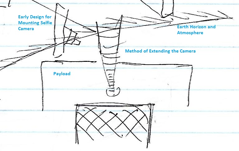
How Do I Extend and Retrieve a Camera From a Payload?
The design and construction of a payload is challenging. Designing and constructing a payload with an electro-mechanical arm controlled from the ground is, in hindsight, ambitious.
My first approach to this design question was to use a long, threaded metal dowel rod known as a lead screw. I bought a three foot lead screw at Home Depot and attached it to my power drill. I discovered it required too much time to extend and retrieve a camera. While there were lead screws available with steeper threading to improve the out-and-back time, they were expensive. Also, I was hesitant to have a lead screw protruding from the payload for the whole flight.
During my research for alternatives, I found a design using PVC pipes. One PVC pipe fit inside another and was made to move out and back using string and a winch. An accompanying video showed this in a small, underwater, remote control vessel, but I thought the design could be adapted for my mission’s purpose.
But Weight
As the final components of the payload were identified, I had a concern about weight. After reviewing the regulations, I bought a scale. With just four months before the start of Summer, the payload needed to lose weight.
I drilled many, many holes in the PVC pipes, found lighter batteries, found lighter rip-stop nylon, used Styrofoam in place of foam core, changed the shape of the payload from a cube to fit the form of the arm, and split the payload into separate enclosures (a Primary and a Secondary). Finally, the mission payload was ready to fly.
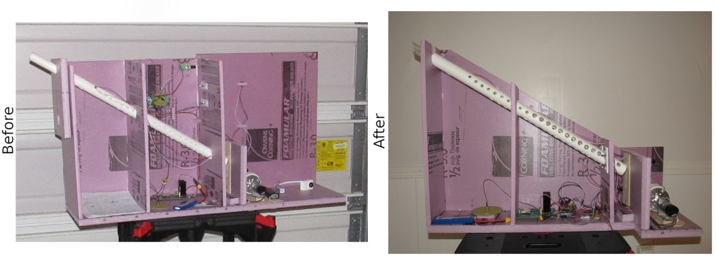
At right, the payload is shown after the weight reduction effort and before the port walls were added.
20 Jul 2019, Flight Day
We arrived at the launch site early. As the launch team started inflating the balloon, I prepared the payload nearby. The stack included the Primary payload (contains the arm assembly and winch, GPS, the Selfie camera, and a witness camera), a Secondary payload (connected to the Primary by an umbilical of wires; contains the flight computer, radio, and antenna), a back-up tracking payload, and a cut down assembly (a back-up flight termination method). When it was ready, I assembled the launch team for a quick picture using the Selfie Sequence.
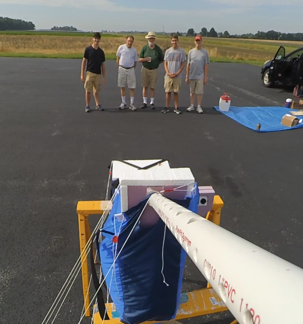
By late morning, surface winds had picked up and were blowing the balloon around. When the inflation was complete, we heard a small hissing sound. Having discovered a small hole in the balloon, we scrubbed the mission.
20 Aug 2019, Flight Day Again
The alarm felt early as it always did on flight day. I slept a little that night and I was apprehensive. I had looked forward to launching this very complex payload for five years. If you have launched a weather balloon payload, you know what this day means.
I prepared the payload stack as I did the month before. The balloon inflation completed quickly and without incident. Using a smaller balloon and more Hydrogen, there was a determined pull upwards and was the reason I brought a cement block. However, even after securing the balloon to the cement block someone had to sit on the block until launch time.
While we were waiting for the GPS to lock, we heard an odd scratching sound. I looked at the block and saw the latch pin had not been latched. The tug of the balloon had deformed the latch pin and scraped it against the cement block. Having nearly lost the balloon, we fixed the latch pin and secured it again.
When we closed the payload hatch, the control program showed the payload was online and the GPS was locked. We removed the balloon from the cement block and attached it to the stack. We carefully allowed the balloon to lift each component until I held the Primary payload. I walked to an open area of the tarmac and looked up. Countless hours of effort were about to journey into the upper atmosphere. I let go of my payload.

Time paused as we watched the balloon ascend into the blue sky. I noticed it was rising fast so I jogged to my laptop and clicked the Selfie button but the control program showed no reaction. I realized the payload was offline. I pointed the long range but narrow beamed Yagi antenna towards my payload but could not re-establish the connection.
I received tracking data from the back-up tracking system for the next 90 minutes as we chased the balloon. We stopped many times to aim the Yagi and attempt a selfie without success. As the flight continued, my thoughts were, unfortunately, planning another launch.
We recovered the payload in a bean field (normal for a late Summer flight in Ohio). The failure to take a selfie was disappointing but I was happy to have launched and retrieved the payload without damage. It could fly again.
Once home, I inspected the payload. The power cable to the radio had disconnected. It may have been that the umbilical from the Primary to the Secondary payload was too short or the strings supporting the Secondary were too long.
Could It Be?
We reviewed the video from the Primary payload’s witness camera (mounted on the side of the payload). The files on the SD card showed it recorded the entire flight. We started with the burst thinking it would be the most interesting. In the near silence of high altitude, we heard a pop. The payload pitched upwards giving us a view of the balloon remnants against the bright sun. As the payload pitched back down and stabilized, air whistled by the camera as the payload accelerated towards Earth.
About a minute later, the arm suddenly extended from the payload. I was concerned that the force from the air rushing past it was pulling it out. Since the arm was inside when the payload landed, we knew this was not true. After ten seconds, the arm retracted. That sequence looked very familiar.
We scrambled to get the SD card out of the Selfie camera and into the computer, silently realizing what we might find. There were two recordings.
We opened the first. An out-of-focus white blob. Then, a small click and low buzzing played over the speakers as the view opened to show the payload and a quilt of green behind it. I had the first selfie.

We checked the second recording. A bassy wind rush roared out of the speakers as the camera extended to show the payload photo-bombed by the Earth and darkness of space. I was overwhelmed, elated, and confused. Without radio contact, how could the selfie sequence have executed?

Epilogue
Not satisfied with just having the selfies, I wanted to know how I got them. I set up the payload to match the flight configuration. After powering it up, I tried to induce noise into the payload wiring in an effort to trigger the Selfie Sequence. No matter what I tried, I was unable to trigger it. I am not certain how the Selfie Sequence was triggered during the flight.
In the last year, I reflected on this experience. In addition to having no control of the Selfie Sequence, I could not monitor position, altitude, payload temperature or battery voltages from the primary tracking system. If I considered another mission, I thought I would capture this data on-board to back up the telemetry. I also thought it might be interesting to have an accelerometer to show both rate change and changes in payload pitch.
While I demonstrated the ability of the flight computer to do both of those on the bench, I confess to a certain amount of satisfaction with my fortune in capturing a payload performing its function. Still, I have a lingering curiosity about the hardware that was not demonstrated. Another flight? We’ll see.
A Word of Thanks
A weather balloon flight is not possible without a great team.
- Thanks Tim for helping get the Hydrogen!
- Thanks Doug for the use of some special tools!
- Thanks to Natasha for the Secondary payload and back up telemetry payload jackets!
- Thanks to Nino for the guidance, patience, and final construction of the Primary Payload jacket!
Flight Day was not possible without the help of this special crew.
- Thanks to Wyandot County Airport for their hospitality!
- Thanks to Dave and Tom for your contributions to the flight!
- Thanks to my family for their support and assistance!
Flight statistics and technical details are provided below.
Flight Statistics
| Flight Designation | Surfs Up 9 |
| Launch Time | 11:20 AM, 20 Aug 2019 Upon review of the flight computer data (498 data points), the launch was closer to 11:23:33. |
| Landing Time | 1360 ft/min (final descent rate based on last two packets) 3783 ft (last reported altitude) To reach the landing site elevation, the payload fell for another 2:47. The last time reported was 13:03:21. The calculated landing time is 13:06:29. Witness 1 YDXJ0423.mp4 starts at 12:54:03. Landing is time stamp 11:17. The calculated landing time is 13:05:20. Selfie YDXJ1731.mp4 starts at 12:54:52. Landing is time stamp 10:29. The calculated landing time is 13:05:21. |
| Recovery Time | The video YDXJ1734.mp4 begins at 13:26:37. Dave yells “Here” at the 8:19 mark. That makes discovery at 13:34:56. Recovery begins about two minutes later. Team members removed the payload from the bean field. The payload was placed into the van around 13:55. |
| Maximum Height | The APRS packet time-stamped at 12:33:12 showed an altitude of 92024 ft. The next packet, 120 seconds later, showed an altitude of 76854 ft. For the values shown, the initial descent rate is over 7500 ft/min. This is common after a burst. I’m concluding the maximum altitude was not much higher than 92024 ft. Based on the ascent rate between the previous packet and the highest altitude packet, the payload may have continued to rise another seven feet. |
| Initial Ascent Rate | The first two APRS packets show an altitude of 2559 ft (11:24:54) and 5062 ft (11:26:54) respectively. The initial ascent rate was 1251 ft/min. |
| Average Descent Rate | 12:33:12; 92024 ft (maximum altitude) 13:03:21; 3783 ft (last packet before landing) Difference is 88241 ft. Time difference is 30:09 (1809 seconds). Average: 48.77 ft/s, 2926 ft/min |
| Launch Coordinates | 40.888.66 N, 83.31316 W, elevation of 823 ft |
| Landing Coordinates | 40.7205 N, 82.94466 W, elevation 1020 ft |
| Distance Traveled | 22.5 miles bearing 118 degrees from the launch site |
| Flight Duration | Based on the information from the flight computer for the launch time, the flight duration is 1:42:56. |
| Selfies | 2 Selfies Altitude: 5126 ft (estimated) Video File Start Time: 11:26:47 (from the Selfie SD card) Arm Fully Extended Time: 11:26:57 Arm Retrieved Time: 11:27:12 Altitude: 87346 ft (estimated) Video File Start Time: 12:33:41 (from the Selfie SD card) Arm Fully Extended Time: 12:33:49 Arm Retrieval Begins: 12:33:59 Arm Retrieved Time: 12:34:05 |
| Burst | YDXJ0421.mp4 time stamp: 12:30:48 |
| Cut Down | YDXJ1734.mp4 starts at 13:26:37. The cut down was reset at 11:00:00 and times out after 2.5 hours or 13:30:00. The sound, if detectable, should occur around 3:23 into the recording. The cut down occurs after landing but before recovery. There are clicks in the recording that match the profile of the cut down. A distinct click at 3:55 is followed about 8 seconds (4:03) later with a subtle click. In testing, the cut down was about 30 seconds past the design time out. |
| Battery Status 31 Aug 2019 | Motor Battery: 12.4 volts Remote Radio Battery: 8.0 volts Base Radio Battery: 7.9 volts Base RS-232 Battery: 8.2 volts Flight Computer Battery (top): 3.7 volts Flight Computer Battery (bottom): 3.7 volts Arduino (left): 3.9 volts Arduino (right): 3.9 volts Wifi (left): 3.7 volts Wifi (right): 3.7 volts The camera battery levels cannot be measured. All three will be re-charged. |
Technical Details
| Selfie Camera, Witness Camera 1 | Yi Action Camera |
| Witness Camera 2 | Yi 4K Action Camera |
| Radio | Murata (formally RFM) DNT900P 900 MHz Spread Spectrum Wireless Transceiver (this product is presently discontinued at Murata) |
| Antenna, Base Station | Yagi L-COM Model HG906YE |
| Antenna, Payload | Big Wheel Antenna WA5VJB Kent Electronics |
| WiFi | Espressif Systems ESP8266 This chip was used to communicate with the Selfie camera through the Selfie Module. |
| Gear Motor | Cytron SPG30-150K 12 volts 26 RPM 588 mN-m torque |
| GPS | Falcom |
| Flight Computer | Arduino Pro Mega, 5 volts |
| Selfie Module | Arduino Pro Mini, 3.3 volts |
| Cut Down | Arduino Pro Mini, 5 volts |
| Batteries | Radio: Turnigy 3300 mAh LiPo, 7.4 volts Motor: Turnigy 1500 mAh LiPo, 11.1 volts |
| Parachute | Spherachutes 60 inch, Neon Orange and White |
| Balloon | Kaymont HAB-1500 |

That’s simply amazing. What a great project.
Thanks Bruce!
awesome!
Speaking as one of the launch team, without the anxieties of leading the project, it was a fun mission! Glad to see the report.
Thank you sir! Hoping see the same for yours soon!